Friday, September 18, 2020

Transfer FSMO roles using the NTDSUtil tool


Transfer FSMO roles using the NTDSUtil tool

Make sure domain administrator is member of Schema Admins group.

Login as administrator 

First, open the command prompt with administrative privileges.

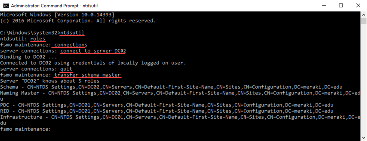
Type ntdsutil and press Enter.
Type roles and press Enter.
Type connections and press Enter.
Type connect to server DC01 and press Enter, where DC01 is the server computer name that will transfer the FSMO roles to.
Type quit and press Enter.

Next, we will transfer FSMO roles one by one with the corresponding command, as the case may be. After each Enter appears a confirmation window. Just click Yes to continue.

For Schema Master, type transfer schema master and press Enter.
For RID Master, type transfer rid master and press Enter.
For Domain Naming Master, type transfer naming master and press Enter.
For PDC Emulator, type transfer pdc and press Enter.
For Infrastructure Master, type transfer infrastructure master and press Enter.

Transfer FSMO roles to another Domain Controller

After transferring the roles you want, press quit to exit the NTDSUtil environment.

Check status in command line 

netdom query fsmo


Wednesday, March 4, 2020

Windows Server convert Evaluation to Licensed version


Windows  Server convert Evaluation to Licensed version

Windows  Server is available as 180-day trial for testing purposes and when the evaluation period expires, the machine stops working properly.
Since the trial is an Evaluation edition, the installed version cannot be licensed as a paid edition but needs to be converted first.
When you try to enter the product key, the following message is displayed:

Verify current version
To display the current installed version, open an elevated Command Prompt and type the command:
C:\>DISM /online /Get-CurrentEdition
In this example, a Server Standard Evaluation edition is installed in the system. To check the Windows version, you can also use the command winver:
C:\>winver

Convert Evaluation to Licensed version
To activate Windows Server with your product key, you need to convert the Evaluation version to Licensed. To check available versions type the following command from an elevated Command Prompt:
C:\>DISM /online /Get-TargetEditions
§  ServerStandard
§  ServerDatacenter
To convert the version, type the command:
DISM /online /Set-Edition:<edition ID> /ProductKey:XXXXX-XXXXX-XXXXX-XXXXX-XXXXX /AcceptEula
C:\>DISM /online /Set-Edition:ServerStandard /ProductKey:XXXXX-XXXXX-XXXXX-XXXXX-XXXXX /AcceptEula
To complete the operation, type Y to restart the computer.
When the server has rebooted, check the installed version with the command:
C:\>DISM /online /Get-CurrentEdition
The Server edition is now a licensed version. Also using the winver command, the window displays the correct licensed version.
Windows has been activated successfully.
This procedure will only work if a KMS host is running on your network with KMS configured correctly.


Friday, August 16, 2019

LACP bonding and Linux configuration

following configuration collected from other blogs.
This blog introduces Link Aggregation Control Protocol (LACP) bonding and provides step-by-step configuration of LACP bonding on Red Hat Enterprise Linux (RHEL) and CentOS operating systems versions 6 and 7.

Introduction

Network bonding enables the combination of two or more network interfaces into a single-bonded (logical) interface, which increases the bandwidth and provides redundancy. If a specific network interface card (NIC) experiences a problem, communications are not affected significantly as long as the other slave NICs remain active.

Bonding modes supported by RHEL and CentOS operating systems

The behavior of the bonded interfaces depends on the mode that is selected. RHEL supports the following common bonding modes:
  • Mode 0 (balance-rr): This mode is also known as round-robin mode. Packets are sequentially transmitted and received through each interface one by one. This mode provides load balancing functionality.
  • Mode 1 (active-backup): This mode has only one interface set to active, while all other interfaces are in the backup state. If the active interface fails, a backup interface replaces it as the only active interface in the bond. The media access control (MAC) address of the bond interface in mode 1 is visible on only one port (the network adapter), which prevents confusion for the switch. Mode 1 provides fault tolerance.
  • Mode 2 (balance-xor): The source MAC address uses exclusive or (XOR) logic with the destination MAC address. This calculation ensures that the same slave interface is selected for each destination MAC address. Mode 2 provides fault tolerance and load balancing.
  • Mode 3 (broadcast): All transmissions are sent to all the slaves. This mode provides fault tolerance.
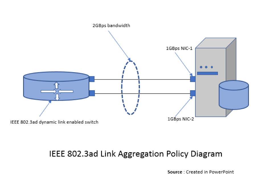
  • Mode 4 (802.3ad): This mode creates aggregation groups that share the same speed and duplex settings, and it requires a switch that supports an IEEE 802.3ad dynamic link. Mode 4 uses all interfaces in the active aggregation group. For example, you can aggregate three 1 GB per second (GBPS) ports into a 3 GBPS trunk port. This is equivalent to having one interface with 3 GBPS speed. It provides fault tolerance and load balancing.
  • Mode 5 (balance-tlb): This mode ensures that the outgoing traffic distribution is set according to the load on each interface and that the current interface receives all the incoming traffic. If the assigned interface fails to receive traffic, another interface is assigned to the receiving role. It provides fault tolerance and load balancing.
  • Mode 6 (balance-alb): This mode is supported only in x86 environments. The receiving packets are load balanced through Address Resolution Protocol (ARP) negotiation. This mode provides fault tolerance and load balancing.

IEEE 802.3ad Link Aggregation Policy and LACP

Before we explore LACP configuration, we should understand the IEEE 802.3ad link aggregation policy and LACP bonding, which allows us to aggregate multiple ports into a single group. This process combines the bandwidth into a single connection.
IEEE 802.3ad link aggregation enables us to group Ethernet interfaces at the physical layer to form a single link layer interface, also known as a link aggregation group (LAG) or bundle.
Some users require more bandwidth in their network than a single fast Ethernet link can provide. Using IEEE 802.3ad link aggregation in this situation provides increased port density and bandwidth at a lower cost.
For example, if you need 2 GBPS bandwidth to transmit data and have only 1 GBPS Fast Ethernet links installed on your system, creating a LAG bundle containing two 1 GBPS Fast Ethernet links is more cost-effective than purchasing a single 2 GBPS Ethernet link.
The following diagram illustrates the IEEE 802.3ad link aggregation policy:
LACP is a mechanism for exchanging port and system information to create and maintain LAG bundles. The LAG bundle distributes MAC clients across the link layer interface and collects traffic from the links to present to the MAC clients of the LAG bundle.
LACP identifies the MAC address of the Ethernet link that has the highest port priority and is of the lowest value, and it assigns that MAC address to the LAG bundle.
This bonding mode requires a switch that supports IEEE 802.3ad dynamic links.

Steps to configure LACP bonding

Preparation: Collect the required details to configure bonding. We recently implemented on production servers the scenario shown in the following table. We changed the IP address, MAC, and UUID details to maintain security.
Bond interface          bond1
Bonding type802.3ad
Bonding optionsmiimon=100,lacp_rate=fast,xmit_hash_policy=layer2+3
Slave interfacesp5p1 p5p2
MTU9000
IP address/prefix179.254.0.2/16

The following sections show the steps to configure LACP bonding by using the command line interface (cli) and the NetworkManager command line interface (nmcli) tools.

STEPS TO CONFIGURE LACP BONDING ON RHEL OR CENTOS 6 BY USING THE CLI TOOL

  1. Backup the existing interfaces before you configure the bonding. Bring $slave1 and $slave2 down and move these files to a backup directory by using the following commands:
    ~]# ifdown p5p1 ; ifdown p5p2
    ~]#cd /etc/sysconfig/network-scripts
    ~]#mv -v ifcfg-p5p1 ifcfg-p5p2 ~/BACKUPDIR
    
  2. Make sure module bonding is loaded by using the following command. You can also load the module with the command #modprobe bonding.
    ~]# lsmod |grep -i bonding
    bonding               145728  0
    
  3. Create the file ifcfg-bond1 and modify the configuration by using the following commands:
    ~]#cd /etc/sysconfig/network-scripts
    ~]#cat ifcfg-bond1
    DEVICE=bond1
    TYPE=Ethernet
    ONBOOT=yes
    USERCTL=no
    NM_CONTROLLED=no
    MTU=9000
    BOOTPROTO=static
    IPADDR=179.254.0.2
    PREFIX=16
    DNS1=<DNS_IP>
    BONDING_OPTS="mode=802.3ad miimon=100 lacp_rate=fast xmit_hash_policy=layer2+3"
    
  4. Modify the slave interface (slave1 and slave2) configurations by using the following commands:
    ~]#cat ifcfg-p5p1
    DEVICE=p5p1
    BOOTPROTO=none
    ONBOOT=yes
    SLAVE=yes
    USERCTL=no
    NM_CONTROLLED=no
    MASTER=bond1
    
    ~]#cat ifcfg-p5p2
    DEVICE=p5p2
    BOOTPROTO=none
    ONBOOT=yes
    SLAVE=yes
    USERCTL=no
    NM_CONTROLLED=no
    MASTER=bond1
    
  5. Restart the network or restart the server by using one of the following commands:
    ~]# service network restart
    
    or
    
    ~]# init 6
    
  6. After the service or server restart, check the proc for a bond interface by using the following command:
    ~]# cat /proc/net/bonding/bond0
    Ethernet Channel Bonding Driver: v3.7.1 (April 27, 2011)
    
    Bonding Mode: IEEE 802.3ad Dynamic link aggregation
    Transmit Hash Policy: layer2+3 (2)
    MII Status: up
    MII Polling Interval (ms): 100
    Up Delay (ms): 0
    Down Delay (ms): 0
    
    802.3ad info
    LACP rate: fast
    Min links: 0
    Aggregator selection policy (ad_select): stable
    Active Aggregator Info:
      Aggregator ID: 1
      Number of ports: 1
      Actor Key: 9
      Partner Key: 550
      Partner Mac Address: 00:24:04:ef:bc:76
    
    Slave Interface: p5p1
    MII Status: up
    Speed: 1000 Mbps
    Duplex: full
    Link Failure Count: 0
    Permanent HW addr: b4:b5:3f:8d:53:77
    Aggregator ID: 1
    Slave queue ID: 0
    
    Slave Interface: p5p2
    MII Status: up
    Speed: 1000 Mbps
    Duplex: full
    Link Failure Count: 0
    Permanent HW addr: b4:b4:2f:5e:55:7b
    Aggregator ID: 2
    Slave queue ID: 0
    
  7. Execute ifconfig -a and check that your bond1 interface is active.
This completes the configuration of LACP bonding on RHEL or CentOS 6 by using the cli tool.

STEPS TO CONFIGURE LACP BONDING ON RHEL OR CENTOS 7 BY USING THE NMCLI TOOL

  1. Backup the existing interfaces that you plan to configure as bond slaves by using the following commands:
    ~]# ifdown p5p1 ; ifdown p5p2
    ~]#cd /etc/sysconfig/network-scripts
    ~]#mv -v ifcfg-p5p1 ifcfg-p5p2 ~/BACKUPDIR
    
  2. Check the status of the interfaces to be configured as bond slaves by using the following commands:
    ~]#nmcli con
    NAME        UUID                                  TYPE            DEVICE
    bond0       f249c64d-724d-416f-aee9-513ad8b6a84b  bond            bond0
    em1         20546e2b-a369-4f75-a4f3-0575d48862c3  802-3-ethernet  em1
    em2         9a2d2ea6-c865-4f7c-856c-1cc2bbf69449  802-3-ethernet  em2
    p5p1        5e377cb8-56ce-4979-882d-4b31a0cdc645  802-3-ethernet  --
    p5p2        9cc9a280-295d-4344-be6b-6e69cd1c20b2  802-3-ethernet  --
    
    ~]# ethtool p5p1 |grep "Link detected"
    Link detected: yes
    ~]# ethtool p5p2 |grep "Link detected"
    Link detected: yes
    
  3. Create a bond connection by using the bonding options in the preceding preparation table and run the following command for a private network:
    ~]#nmcli con add type bond con-name bond1 ifname bond1 mode 802.3ad ipv4 179.254.0.2/16
    Connection 'bond1' (5a21933b-0c60-4aa6-93b2-b0e4dab6747e) successfully added.
    
    ~]#nmcli con mod id bond1 bond.options mode=802.3ad,miimon=100,lacp_rate=fast,xmit_hash_policy=layer2+3
    ~]#nmcli con mod id bond1 802-3-ethernet.mtu 9000
    ~]#nmcli con add type bond-slave ifname p5p1 con-name p5p1 master bond1
    Connection 'p5p1' (5e377cb8-56ce-4979-882d-4b31a0cdc645) successfully added.
    
    ~]#nmcli con add type bond-slave ifname p5p1 con-name p5p2 master bond1
    Connection 'p5p2' (9cc9a280-295d-4344-be6b-6e69cd1c20b2) successfully added.
    
3.5 If you want to setup a bond for public network, you must run the following command instead:
    ~]#nmcli con add type bond con-name bond1 ifname bond1 mode 802.3ad ipv4 179.254.0.2/16 gw <your_gateway>
  1. Restart the NetworkManager service by using the following command:
    ~]#systemctl restart NetworkManager
    
  2. Check the status of the bond and slave interfaces to verify that the bond1 interface is running by using the following commands:
    ~]#nmcli con
    NAME        UUID                                  TYPE            DEVICE
    bond0       f249c64d-724d-416f-aee9-513ad8b6a84b  bond            bond0
    em1         20546e2b-a369-4f75-a4f3-0575d48862c3  802-3-ethernet  em1
    em2         9a2d2ea6-c865-4f7c-856c-1cc2bbf69449  802-3-ethernet  em2
    p5p1        5e377cb8-56ce-4979-882d-4b31a0cdc645  802-3-ethernet  p5p1
    p5p2        9cc9a280-295d-4344-be6b-6e69cd1c20b2  802-3-ethernet  p5p2
    bond1       5a21933b-0c60-4aa6-93b2-b0e4dab6747e  bond            --
    
    ~]# nmcli con up uuid 5a21933b-0c60-4aa6-93b2-b0e4dab6747e
    Connection successfully activated (master waiting for slaves) (D-Bus active path: /org/freedesktop/NetworkManager/ActiveConnection/8)
    
    ~]#nmcli con
    NAME        UUID                                  TYPE            DEVICE
    bond0       f249c64d-724d-416f-aee9-513ad8b6a84b  bond            bond0
    bond1       5a21933b-0c60-4aa6-93b2-b0e4dab6747e  bond            bond1
    em1         20546e2b-a369-4f75-a4f3-0575d48862c3  802-3-ethernet  em1
    em2         9a2d2ea6-c865-4f7c-856c-1cc2bbf69449  802-3-ethernet  em2
    p5p1        5e377cb8-56ce-4979-882d-4b31a0cdc645  802-3-ethernet  p5p1
    p5p2        9cc9a280-295d-4344-be6b-6e69cd1c20b2  802-3-ethernet  p5p2
    
  3. After the configuration is complete, check the output of the following commands to verify that the bond1 interface is active and no error is found:
    ~]#cat /proc/net/bonding/bond1
    Ethernet Channel Bonding Driver: v3.7.1 (April 27, 2011)
    
    Bonding Mode: IEEE 802.3ad Dynamic link aggregation
    Transmit Hash Policy: layer2+3 (2)
    MII Status: up
    MII Polling Interval (ms): 100
    Up Delay (ms): 0
    Down Delay (ms): 0
    
    802.3ad info
    LACP rate: fast
    Min links: 0
    Aggregator selection policy (ad_select): stable
    .
    .
    .
    Output truncated
    
    ~]#cat /sys/class/net/bond1/bonding/mode
    802.3ad 4
    
    ~]# ip a s
    .
    .
    .
    6: p5p1: <BROADCAST,MULTICAST,SLAVE,UP,LOWER_UP> mtu 9000 qdisc mq master bond1 portid 3cfdfe240520 state UP qlen 1000
        link/ether 3e:fc:fb:24:06:30 brd ff:ff:ff:ff:ff:ff
    7: p5p2: <BROADCAST,MULTICAST,SLAVE,UP,LOWER_UP> mtu 9000 qdisc mq master bond1 portid 3cfdfe240522 state UP qlen 1000
        link/ether 3e:fc:fb:24:06:30 brd ff:ff:ff:ff:ff:ff
    9: bond1: <BROADCAST,MULTICAST,MASTER,UP,LOWER_UP> mtu 9000 qdisc noqueue state UP qlen 1000
        link/ether 3e:fc:fb:24:06:30 brd ff:ff:ff:ff:ff:ff
        inet 179.254.0.2/16 brd 169.254.255.255 scope link bond1
    
This completes the process of LACP bonding on RHEL or CentOS 7 by using the nmcli tool.

Conclusion:

If you need more bandwidth in your network than a single NIC can provide, LACP bonding is very useful. Using IEEE 802.3ad link aggregation in this situation provides increased port density and bandwidth. For more options, refer to the nmcli documentation.

Friday, August 3, 2018

How to Configure Folder Redirection in Windows Server 2016


How to Configure Folder Redirection in Windows Server 2016
What is Folder Redirection? 
This article shows you how simply you can redirect folder in Windows Server with group policy. The folder redirection is the way to keep a profile folders to a network location or other location in the local computer. Typically user profiles and settings are stored in local profile. By redirecting folders, you can  access to data regardless of which computers you are logs in.
In addition to the immediate benefit of having that data on a file server that is much easier to keep backed up, the user also gets the benefit of being able to go to multiple computers in your organization and still have access to their data. Using the default Windows settings and the default share settings on your file server, these redirection will be even made available offline automatically for your users.
The Policy-Based QoS node
This quality of service (QoS) node, known as the Policy-Based QoS node, defines policies that manage network traffic. For example, you might want to ensure that users in the Finance department have priority to run a critical network application during the end-of-year financial reporting period. You can do that by using the Policy-Based QoS node.
In the User Configuration node only, the Windows Settings folder contains the additional Folder Redirection node. With folder redirection, you can redirect user data and settings folders such as AppData, Desktop, Documents, Pictures, Music, and Favorites from their default user profile location to an alternate location on the network, where you can manage them centrally.
Infrastructure Requirement :
·         1 DC SERVER (EXAMPLE-DC01) 
·         Client PC running Windows 10 (CLIENT-10)
Lets get started.
01 – Create a Shared Folder
1 – On EXAMPLE-DC01, on the taskbar, click the File Explorer icon, In the navigation pane, click This PC. 

2 – In the details pane, double-click Local Disk (C:), and then on the Home tab, click New folder.
3 – In the Name text box, type Redir, and then press Enter.
2.png
3.png
4 – Right-click the Redir folder, click Share with, and then click Specific people.
4.png
5 – In the File Sharing dialog box, click the drop-down arrow, select Everyone, and then click Add.
6.png
6 – For the Everyone group, click the Permission Level drop-down arrow, and then click Read/Write.
5.png
7 – Click Share, and then click Done.
7.pngClose the Local Disk (C:) window
02 – Create a GPO to redirect the Documents folder
1 –  In Server Manager, click Tools and then click Group Policy Management.

19
2 – In the navigation pane, right-click the Windows.ae domain, and then click Create a GPO in this domain and Link it here.
8.png
3 – In the New GPO dialog box, in the Name text box, type Folder Redirection, and then click OK.
9.png
4 – In the navigation pane, right-click Folder Redirection, and then click Edit.
10.png
5 – In the Group Policy Management Editor window, under User Configuration, expand Policies,expand Windows Settings, and then expand Folder Redirection.
11.png
6 – Right-click Documents, and then click Properties.
12.png
7 – In the Document Properties dialog box, on the Target tab, click the Setting drop-down arrow, and then select Basic-Redirect everyone’s folder to the same location.
13.png
8 – Ensure that the Target folder location box is set to Create a folder for each user under the root path.
14.png
9 – In the Root Path text box, type \\EXAMPLE-DC01\Redir, and then click OK.
15.png
10 – In the Warning dialog box, click Yes.
16.pngClose the Group Policy Management Editor
03 – Test Folder Redirection
1 –  Sign in to CLIENT-10 as Windows\Administrator with the password asd@123. 

32
2 – Right-click Start, and then click Command Prompt.
5
3 – In the Command Prompt window, type the following command, and then press Enter:
Gpupdate /force
17.png
4 – In the command prompt window, when prompted, type the following, and then press Enter:
Y
18.png
5 – Sign in to CLIENT-10 as Windows\Administrator with the password asd@123.
32
6 – On the taskbar, click the File Explorer icon. 

19.png
7 – In the navigation pane, in the Quick Access section, right-click Documents, and then click Properties.
20.png
8 – Verify that on the General tab, the Location field has a value of \\EXAMPLE-DC01\redir\Administrator.
21.pngIf this is not successful, repeat steps 2 through 7, and then check the redirection once again.
9 – Sign out of CLIENT-10.